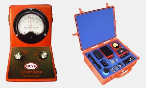
DCVG Survey Equipment
Price 50 INR/ Unit
DCVG Survey Equipment Specification
- Capacity
- 8 hours continuous operation
- Equipment Type
- DC Voltage Gradient Survey Equipment
- Humidity %
- 0% to 95% (non-condensing)
- Temperature Range
- -10C to +55C
- Measurement Range
- 0 mV to 2000 mV
- Current Range
- 0 - 20 mA
- Frequency
- DC only
- Connectivity Type
- USB data output
- Resolution
- 1 mV
- Sensor Type
- High input impedance voltage probe
- Material
- Rugged ABS housing
- Power Supply
- Internal rechargeable lithium-ion battery, 7.4V DC
- Power Consumption
- Low power, standby mode enabled
- Accuracy
- 1% of reading
- Display Type
- Backlit digital LCD
- Range
- 0 mV to 2000 mV
DCVG Survey Equipment Trade Information
- Minimum Order Quantity
- 1 Unit
- Supply Ability
- 500 Units Per Day
- Delivery Time
- 1 Days
- Main Export Market(s)
- Western Europe, Australia, North America, South America, Eastern Europe, Middle East, Africa, Central America, Asia
- Main Domestic Market
- All India
About DCVG Survey Equipment
Caltech India offers basic and standard DCVG equipment. DCVG-UK manufactured useful equipment. when DC is applied to a pipeline in the same manner as in cathodic protection, a voltage gradient is established in the ground due to the passage of current through the resistive soil to the bare steel exposed at a coating fault.
The voltage gradient becomes larger and more concentrated the greater the current flowing and the closer you are to a coating fault location. In general, the larger the fault, the greater the current flow and hence bigger the voltage gradient.
The direct current voltage gradient method (DCVG) uses a sensitive mili-volt meter, to indicate the potential difference between two copper/copper sulphate half cells placed in the soil in the voltage gradient at ground level. If spaced two metres apart in a voltage gradient, one half cell will adopt a more positive potential than the other, which thus enables the size of the gradient and direction of the current flow causing the voltage gradient to be established.
To make it easier to interpret and to separate what is being monitored from other DC sources such as long line cells, telluric, other CP systems, etc., in the DC Voltage Gradient Technique, the asymmetrical DC signal impressed onto the pipeline is switched ON and OFF at the rate of 0.45 seconds ON, 0.8 seconds OFF. The DC signal can be impressed on top of existing CP systems or the pipeline CP Transformer Rectifiers (T/R) can be switched by using a special interrupter inserted into the negative lead from the Transformer Rectifier.
Precision Voltage Gradient Detection
Designed to provide reliable voltage gradient measurements, this equipment features a high input impedance voltage probe, ensuring accurate field readings. Measurement is hassle-free, with user-friendly controls and a clear, backlit LCD display for various lighting conditions. The 1% accuracy and 1 mV resolution make it ideal for critical corrosion assessment tasks.
Built for Challenging Field Conditions
Encased in rugged ABS material, the equipment withstands demanding outdoor environments. Its waterproof and impact-resistant carrying case protects it during transport and use. The 5-meter probe cable allows flexibility, while the system operates efficiently in temperatures from -10C to +55C and high humidity (095%).
User-Centric Design and Extended Capability
With both manual and automatic calibration options and on-board data storage for up to 1000 readings, users can manage extensive survey data efficiently. The internal lithium-ion battery supports 8 hours of continuous work, while USB connectivity allows easy data export and reporting, enhancing workflow and productivity.
FAQs of DCVG Survey Equipment:
Q: How do I operate the DCVG Survey Equipment in outdoor field conditions?
A: The DCVG Survey Equipment is engineered specifically for outdoor use with a rugged ABS housing and waterproof, impact-resistant carrying case. Simply assemble the probe, connect the 5-meter cable, power on the device using the rechargeable lithium-ion battery, and follow the on-screen prompts to begin measuring voltage gradients.Q: What is the calibration process for this DCVG Survey Equipment?
A: You can calibrate the equipment either manually or automatically. Manual calibration allows for user control, while auto calibration streamlines the process. Calibration ensures accurate readings and should be done periodically, especially after significant environmental changes or extended storage.Q: When should data be transferred from the device, and how is it done?
A: Data can be stored onboard up to 1000 readings. It is advisable to export data to a computer regularly using the USB data output, especially after each field survey to ensure records are backed up and ready for analysis or reporting.Q: Where can this equipment be deployed most effectively?
A: This device excels in environments requiring durable, precise voltage measurement, such as pipeline corrosion surveys, electrical utilities, and industrial inspection locations across various field conditions in India.Q: What benefits does the manual and auto calibration feature offer?
A: Manual calibration offers flexibility for experienced users to fine-tune the device, while auto calibration ensures quick, consistent accuracy in dynamic field conditions, enhancing reliability and efficiency during extended surveys.Q: How long does the battery last during field operations, and how is it recharged?
A: The internal rechargeable lithium-ion battery provides up to 8 hours of continuous use. Recharging is straightforwardsimply connect the device to the supplied charger or USB power supply, ensuring extended availability during long field sessions.Q: What distinguishes this equipment from other voltage gradient survey tools?
A: Its compact size, robust environmental resistance, high accuracy (1%), user-selectable voltage reference, and substantial data storage capacity, combined with low power consumption and advanced calibration modes, set it apart for demanding professional applications.

Price:
- 50
- 100
- 200
- 250
- 500
- 1000+
More Products in Data Logger & CP Survey Equipment Category
GPS Synchronized Smart Data Logger
Price 50 INR / Piece
Minimum Order Quantity : 50 Pieces
Application Media : Water, Air, Industrial Gases
Power Consumption : Less than 5W
Flow Rate : With compatible sensor
Material : ABS Plastic Enclosure

 Send Inquiry


 Send Inquiry
 Send SMS